Heat Pipes and Two-Phase Cooling Systems
Heat Pipes
One of the main jobs of a spacecraft thermal system is to cool electronics boxes, lasers, and other devices that produce heat. Sometimes, this is done by attaching those devices directly to the radiator panels, which send the heat into space as infrared radiation. In other cases, the heat needs to be carried some distance to the radiator panels. In some cases, a bar of copper or of some other highly conductive material carries the heat well enough. In other cases, we use heat pipes or similar techniques. A heat pipe is one example of a two phase cooling system, that is, a system which uses both the liquid phase and the vapor phase of a material.
A uses evaporation and condensation of a fluid to carry heat. The fluid evaporates in the section of the heat pipe that is attached to the electronics box, laser, or other heat source. The vapor travels down the hollow center of the tube, till it reaches a cold section of the tube, where it condenses. The liquid then flows back to the hot section of the tube, where it vaporizes again.
Loop Heat Pipes
- For information on how Loop Heat Pipes work, see our page.
- Used to cool the laser in the LIDAR system of the Geoscience
Laser Altimeter System (GLAS)
on the Ice, Cloud, and land Elevation Satellite
(ICESAT)
(LIDAR, or LIght Detection and Ranging, is like Radar, but using laser light instead of radio waves.) - Used again to cool the LIDAR on the follow-on ICESAT-2
- EOS-CHEM (Aura); Tropospheric Emission Spectrometer (TES) instrument. (JPL was lead center.) TES operated from 2004 to 2018.
- Multiple members of the Geostationary Operational Environmental Satellite series, including particularly GOES N-Q renumbered after launch as Goes 13-15.
- Burst Alert Telescope (BAT) of the Neil Gehrels Swift Observatory, a mission launched in 2004 to study Gamma Ray Bursts (GRBs)
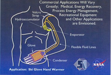
- , designed to heat the hands using heat from the body's trunk, was developed, fabricated, and tested.
- , designed to obtain ice sheet and ocean topography, and global profiles of land and vegetative canopy.
- Capillary Pumped Loop 1 (CAPL 1) Flight test of a full sized capillary pump loop prototype. Flew in 1994 on STS-60.
- (CAPL 2). Prototype of Capillary Pumped Heat Transport for Earth Observing System (EOS)-AM three port, single evaporator Capillary Pumped Loop (CPL). Flew in 1995 on STS-69.
- (CAPL 3). Full scale CPL experiment with multiple bubble tolerant evaporators and direct condensation radiators; demonstrated heat load sharing between evaporators. Flew on STS-108.
- Flight experiment testing advanced features and components in a small scale Capillary Pumped Loop. Flew in 1997 on STS-85.
- (CCQ) was a reflight of the Two Phase Flow Experiment.
- EOS-AM (TERRA); successfully launched December 1999 ---All three CPL loops started up and operated properly.
- Hubble Space Telescope Servicing Mission-3B; March 2002; capillary pumped loop installed as part of the NICMOS cryocooler.
- Mini-CPL/LHP for micro/nanosat applications---some success with ground demo loops; a version flew on the Space Technology 8 (ST8) spacecraft, part of the New Millennium Program. The flight raised the Technology Readiness Level to TRL-6, defined as a model demonstration in a relevant environment.
- For information on how Loop Cryogenic Capillary Pumped Loops work, see our page.
- A CPL with working fluid nitrogen (N2) operating in the range of approximately 75 Kelvin to 90 Kelvin, demonstrated on STS-95
- A CPL with working fluid neon (Ne), operating in the range of approximately 32 K to 38 K, demonstrated in the laboratory.
- A combined Capillary Pumped Loop/Loop Heat Pipe, with working fluid helium, operating near 4 K under consideration for SPECS/SPIRIT application
- (TEMP 2A-3) was a Proof of Concept mission for a mechanically pumped two-phase ammonia thermal control system. It flew in 1992 on STS-46
Traditional Capillary Pumped Loop
The (CPL) is a two-phase heat transport device which utilizes the surface tension force developed in a fine-pore wick to circulate large heat loads over long distances with small temperature differentials and no external pumping power requirements.
Cryogenic Capillary Pumped Loops
Mechanically Pumped Loops
Heat Pipes
How Heat Pipes Work
The Heat Pipe is one of the most utilized systems in space applications for thermal management. "Heat Pipe" is the name given to a high performance heat transfer device which can transport heat at high rates and over relatively long distances with a small temperature difference. For example, heat pipes can passively transport hundreds of watts of heat over several meters with only few degrees temperature drop.
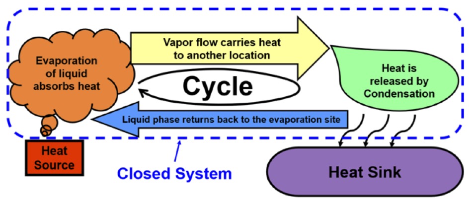
The Heat Pipe's operating principle is based on a closed heat transfer cycle using two phases, liquid and gas. The diagram below shows how heat is transferred from a heat source to a heat sink in a two-phase system.
The left hand end of the diagram shows heat energy being absorbed from a heat source. The right hand end shows heat being dumped into a heat sink.
As heat energy is absorbed, the liquid evaporates, changing the working fluid from the liquid phase to the vapor phase. The vapor phase flows to another section of the heat pipe where it is cooled by a heat sink. The vapor releases the absorbed heat (called "latent heat") as it condenses back into a liquid. The liquid flows back to the heat source location and this cycle continues. To enable the return flow of the liquid, a heat pipe contains a wick structure. The liquid moves through the wick by means of capillary action.
A heat pipe is thus based on a closed two-phase cycle where liquid return accomplished by a wick structure. Therefore, heat pipe also called a "capillary two-phase heat transfer device".
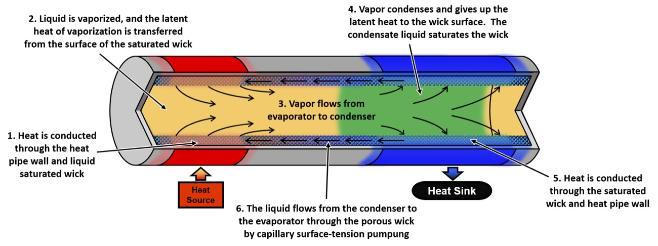
The next figure gives another view of six independent processes which occur simultaneously during the heat pipe operation.
The six independent steps are:
- Heat is conducted from an external heat source through the heat pipe wall and saturated wick.
- Liquid is vaporized, and the latent heat of vaporization is captured from the surface of the wick.
- Vapor flows from the evaporator region to the condenser region.
- Vapor condenses and gives up its latent heat of vaporization on the surface of the wick. The condensed liquid saturates the wick.
- Heat is transferred from the condenser surface through the saturated wick and pipe wall to the external heat sink.
- The condensate liquid flows from the condenser to the evaporator through the wick by capillary surface-tension pumping.
The primary driving force that causes a heat pipe to operate is an externally applied heat load to the evaporator and heat removal from the condenser.
Benefits of Heat Pipes
The main benefits of heat pipes include:- Passive - no external pumping power.
- Self-regulating - no flow control devices.
- No moving parts - vibration free.
- Small temperature difference.
The Three Main Uses for Heat Pipes in Space
Transport heat from one location to another.
Typically, when a transport distance is more than 4 inches (100 mm) and heat load exceeds 1W. For example: an electronic component on a spacecraft generates 5W of heat and it is 30 inches from the radiator.
Provide heat spreading for high heat flux applications.
Heat flux on the order of 10W/cm2 or higher. For example: leading edge of a reentry vehicle.
Create isothermal condition.
Heat pipes become an attractive option when temperature uniformity provides substantial benefits. For example: embedding heat pipes into a radiator panel significantly increases its efficiency. As a result, the radiator size can be reduced.
In some space applications heat pipes are used for more than one purpose listed above.
Typical Fluids Used in Heat Pipes
There are many substances utilized in heat pipes as working fluids. The typical working fluids for space applications include:
- ammonia
- propylene
- ethane
- water
- nitrogen
Ammonia is by far the most used among them due to its wide saturation temperature range (from -77.7 degrees Celsius to +132.4 degrees Celsius), high surface tension and large latent heat of vaporization.
Types of Heat Pipes
Heat pipes are typically divided in the following categories:
- Constant conductance heat pipes
- Variable conductance heat pipes
- Diode heat pipes
- Loop heat pipes
- Capillary pumped loops
- Oscillating heat pipes
- Thermosiphons
In addition, there are many hybrid systems employing heat pipes with other technologies, such as mechanical pumps, phase-change materials, or various pressure regulators.
Contact
Sergey Semenov
GSFC Code 545
(301)
286-3130
Sergey.Y.Semenov@nasa.gov
Heat Pipe Performance Flight Experiments (HPP)
The Heat Pipe Performance (HPP-2) Experiment investigated the thermal performance and fluid dynamics of heat pipes operating under microgravity conditions. The experiment was manifested on STS-66 as a secondary middeck payload, and was launched on November 3, 1994.
The experiment consisted of two different axially grooved, aluminum heat pipes with oxygen as the operating fluid. One of the pipes was provided by the Hughes Aircraft Corporation's Electron Dynamics Division while the other was from TRW. Three "tactical" Stirling cryogenic coolers were used to cool the condenser of the Hughes pipe while two similar coolers were used on the TRW pipe. Simulated thermal loads were provided by electrical resistance heaters. Temperature was measured by PRTs. Extensive efforts were made to provide thermal isolation of the two heat pipes.
HPP Description
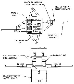
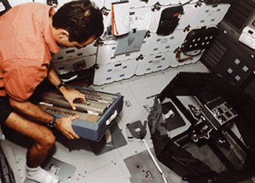
A Thermal Performance Apparatus (TPA) mounted to middeck seat studs allowed the Orbiter crew members to test individual heat pipes in the crew compartment during the flight. Thirty-five tests were to be performed with ten different axially grooved aluminum/freon heat pipes.
The experiment hardware is modular and was stowed in three middeck lockers when not in use.
The heat pipe is very efficient heat transfer device commonly used for cooling electronic components and sensors in spacecraft. A heat pipe is essentially a closed, evacuated tube that is lined with a porous structure called a wick. The wick is saturated with a small quantity of liquid called the working fluid. Heat is absorbed at one end of the heat pipe, evaporating the working fluid contained in the wick structure. This vapor is transported to the heat rejection end of the heat pipe, where the heat is released as the vapor condenses. The condensate is transported back to the heated end of the heat pipe by capillary forces formed in the wick, and the cycle is repeated. It is important to note the evaporative phase change stores heat energy in the vapor at a constant temperature. The vapor will remain at this temperature until it meets a colder surface and condenses. This results in near-isothermal operation, making the heat pipe a very high thermal conductance heat transfer device.
The design of effective spacecraft thermal control systems requires an understanding of heat pipe fluid dynamics in a microgravity environment. This behavior cannot be adequately evaluated on Earth because gravity tends to dominate the capillary forces developed in the wick. In the microgravity environment, however, surface tension forces within the wick become the dominating factor. Additionally, in the absence of gravity, excess fluid in the heat pipe can partially block the condenser, which decreases the thermal transport capability. For these reasons flight experiments are critical for collecting the data necessary for computer model validation.
The original Heat Pipe Performance Flight Experiment (HPP-1) was flown on STS-52 in October, 1992, to investigate and document the microgravity behavior and performance of several different types of heat pipes. Data from HPP-1 was used to modify and validate a NASA heat pipe computer model known as the Groove Analysis Program (GAP). The current version of GAP models heat pipes with single and uniform heating and cooling zones, and is available from the Computer Software Management and Information Center (COSMIC).
The Heat Pipe Performance (HPP-2) flight experiment was an unqualified success. Thanks to the superb efforts of Mission Specialist Jean-Francois Clervoy, Payload Commander Ellen Ochoa, and Commander Don McMonagle, all planned heat pipe tests were successfully performed. Three extra tests were also completed, enabling 100% of our mission objectives to be achieved. These tests have provided the first micro-gravity data for axially grooved heat pipes with asymmetric and distributed heat loads, and with high local heat fluxes. Operation under positive body forces was investigated, and the effects of fluid overfill and underfill were determined. A comprehensive data base now exists for both quantitative correlation and qualitative assessments of axially grooved heat pipe performance in micro-gravity.
The majority of the heat pipe tests yielded the results that were anticipated. Closed groove and open groove heat pipes behave the same in micro-gravity, whereas ground tests show a distinct performance reduction in open groove heat pipes. The maximum heat transport for uniform and distributed heat loads were accurately predicted by GAP. Positive body forces applied to the heat pipes created liquid slugs in the evaporator that decreased the thermal conductance, an effect that became less pronounced as the body force was reduced.
HPP Summary and Results
The effects of asymmetric heating and fluid underfill are the most striking and important results of HPP-2. Preliminary comparisons between uniform and asymmetric heating show a less than 10% reduction in the maximum heat transport capacity, an unexpected but beneficial result. If further, detailed analysis confirms these observations, up to 30% of the performance margin currently specified for operational heat pipes can be recovered through less conservative designs. The need to understand this phenomena is high, since current transport theory indicates physical limits to the heat transfer within the heat pipe that are greater than those revealed during HPP-2. The performance of the underfilled heat pipes was also a great surprise, reflecting a gradual reduction in heat transport capacity with underfill. These results are markedly different from both conventional belief and predictions of the Groove Analysis Program (GAP), highlighting the need for improvements in the off-nominal predictive capabilities of GAP.
The impact of the HPP-2 experiment on the commercial heat pipe community will be high. The higher than expected thermal conductance of heat pipes with asymmetric heat loads will allow design margins (and weight) to be reduced, or payload power can be increased using existing heat pipe thermal control systems. The measured heat flux limit will permit higher power density components to be used with confidence. The apparent insensitivity of the micro-gravity performance of heat pipes to fluid charge will greatly reduce the cost of manufacture by eliminating acceptance tests required to precisely determine fluid charge.
Contact
Sergey Semenov
GSFC Code 545
(301)
286-3130
Sergey.Y.Semenov@nasa.gov
Cryogenic Heat Pipe Flight Experiment
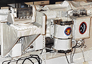
The Cryogenic Heat Pipe Flight Experiment (CRYOHP) represented the first test fight of cryogenic heat pipes operating below 100K. CRYOHP was flown on the shuttle Discovery on flight STS-53 in December of 1992. It was mounted inside a Hitchhiker Canister which allowed real time ground control of the experiment during the mission.
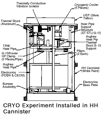
The experiment consisted of two different axially grooved, aluminum heat pipes with oxygen as the operating fluid. One of the pipes was provided by the Hughes Aircraft Corporation's Electron Dynamics Division while the other was from TRW. Three "tactical" Stirling cryogenic coolers were used to cool the condenser of the Hughes pipe while two similar coolers were used on the TRW pipe. Simulated thermal loads were provided by electrical resistance heaters. Temperature was measured by PRTs. Extensive efforts were made to provide thermal isolation of the two heat pipes.
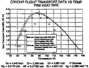
During the six day mission a total of three startup cycles were conducted on each pipe. In addition, maximum heat transport data was obtained over a range of 60K to 140K. Startup in flight was repeatable but slower that on the ground. This is explained by the formation of liquid slugs in the condenser and the lack of liquid "puddling" while on orbit.
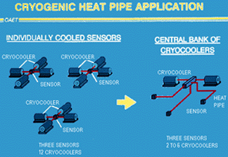
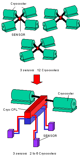
Using cryogenic heat pipes lets the thermal designer reduce the number of cryocoolers needed for a satellite. Some of the sensors designed by Goddard scientists need to be cooled to cryogenic temperatures. Without the cryogenic heat pipes, each sensor would need its own cooler or group of coolers. With the cryogenic heat pipes, one cooler, or one group of coolers, can cool as many sensors as can be connected by the heat pipes.
Drawing: diagram of the Cryogenic Heat Pipe (CRYOHP) Application, showing how it enables reduction in the number of coolers.
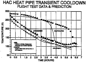
Transport data generally showed good correlation with the theoretical analytical model based on the GAP computer code that was employed to predict performance. GAP's predictions were about 10 to 20% higher than flight data, but this may well be due to the difficulty in eliminating parasitic losses. In summary, all mission objectives were achieved. This effort formed the basis for a follow-on test, the Cryogenic Two-Phase Flight Experiment (CRYOTP).
Reference: Patrick J. Brennan, Lee Thienel, Ted Swanson, and Michael Morgan; "Flight Data for the Cryogenic Heat Pipe (CRYOHP) Experiment," AIAA 28th Thermophysics Conference, AIAA paper No. 93-2735, July 6-9, 1993, Orlando, FL.
Drawing: Inside of the Cryogenic Heat Pipe (CRYOHP) Flight Canister
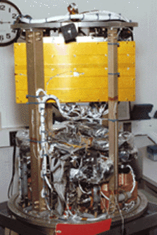
Photo: The Crogenic Heat Pipe (CRYOHP) Flight Canister
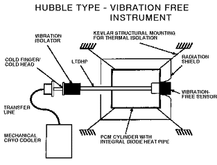
Drawing: Diagram of a Hubble-Type Vibration Free Instrument
Diagram: Graph of Cyrogenic Heat Pipe (CRYOHP) heat transport data as a function of temperature for the TRW heat pipe
Diagram: Graph comparing Flight Data with Predictions
Capilllary Pumped Loops
Basic Operation
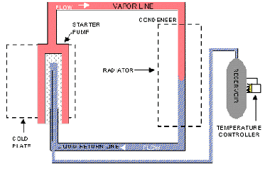
The capillary pumped loop (CPL) is a two-phase heat transport device which utilizes the surface tension force developed in a fine-pore wick to circulate large heat loads over long distances with small temperature differentials and no external pumping power requirements.
A functional schematic of the CPL is illustrated in the above figure. It consists of an evaporator zone, a vapor transport line, a condenser zone, a liquid return line, and a reservoir. The evaporators acquire heat and vaporize the working fluid, while the condensers reject heat and condense the fluid. The vapor transport line and the liquid return line transfer vapor and liquid, respectively, between the evaporator zone and the condenser zone. The reservoir is used for operating temperature control and liquid inventory management. Basic CPL operating principles are as follows: as the evaporator is heated, liquid from the saturated wick evaporates and, at the same time, menisci are formed at the vapor/liquid interface to develop the necessary capillary force to move the fluid around the loop. Vapor generated in the evaporator zone flows to the condenser zone where heat is removed and the vapor condenses. Before returning to the evaporator, the liquid passes through a subcooled section that collapses any remaining vapor bubbles and provides enough subcooling to the fluid to prevent it from vaporizing before reaching the evaporator wicks.
A CPL contains no moving parts and hence is free of vibrations. This increases the reliability of the system. It is a passive and self-regulating device in the sense that each evaporator pump draws as much liquid as required by the heat input to convert all the liquid into vapor.
Applications
The Capillary Pumped Loop has been selected as the baseline thermal control system for several of the Earth Observing (EOS-AM) instruments and has been identified as an enabling technology for future NASA and DoD Missions. It has also has commercial applications which include:
- Medical
- Energy Recovery
- Process Energy Management
- Recreational Equipment
Contact
Sergey Semenov
GSFC Code 545
(301)
286-3130
Sergey.Y.Semenov@nasa.gov
Capillary Pumped Loop 2 (CAPL-2)
The Capillary Pumped Loop 2 (CAPL-2) payload was an in-orbit microgravity demonstration of the full scale capillary pumped loop system planned for (and subsequently used on) the Earth Observing System (EOS) Terra Mission. The CAPL-2 payload flew on STS-69 in September 1995. It was a reflight of the CAPL-1 Hitchhiker payload flown on STS-60 in February 1994, with modifications to enhance the startup of its capillary system. The CAPL-2 flight verified the heat transport requirements of the thermal control system then under design for Terra. The Goddard Space Flight Center Thermal Engineering Branch has developed the Capillary Pumped Loop technology.
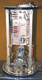
This experiment used an evaporator plate with a capillary pump that vaporized a liquid ammonia working fluid by the use of heaters. The ammonia vapor then traveled through a 3-m long line to heat exchangers, where the vapor was condensed to a liquid and returned to the evaporator plate via an 3-m long liquid line. Heat rejection was accomplished via heat pipes that carried the heat from the heat exchangers to a radiator. A unique feature of the CAPL-2 is that all of the pumping was done by capillary forces, with no mechanical moving parts. The CAPL-2 used separate electronics control modules for telemetry, command, and power. The CAPL-2 electronics were in turn interfaced to the Hitchhiker avionics as a standard, easy-to-use shuttle carrier system. During the mission, a control center at the Goddard Space Flight Center issued commands to the CAPL-2 experiment, monitored its performance, and conducted real-time mission analysis on the CAPL-2 system.
Contact
Laura Ottenstein
(301)
286-4141
Laura.Ottenstein-1@nasa.gov
Capillary Pumped Loop 3 (CAPL3)
The Capillary Pumped Loop 3 (CAPL 3) Flight Experiment is a two-phase
thermal control system that flew on the Space Shuttle on
STS-108. The main objective of this experiment is to demonstrate a multiple
evaporator capillary pumped loop system in micro-gravity. Capillary Pumped Loops (CPL's) are
thermal control systems that utilize a two-phase fluid loop with a porous wick material to
provide the fluid circulation or "pumping". They have no moving parts, yet are capable of
high heat loads with transport distances up to tens of meters.
Current two-phase heat
transfer technology is limited to single pump loops like those flying on the Terra
Spacecraft. CAPL 3's multiple pump loop technology provides numerous heat acquisition sites
and both heat sharing as well as cooling capabilities. The analogy to terrestrial systems is
that multiple pump loops are like a central utility, where single pump loops are similar to
individual room units. The central utility offers higher efficiency and capabilities not
possible with the single pump systems. Use of multiple pump loops on future Spacecraft will
enable higher power levels, tighter temperature control, and will save both heater power and
radiator weight.
The CAPL 3 logo shows the experiment mounted in the center of the Get Away Special bridge which will be located in the payload bay. The letter Q is the thermodynamic symbol for heat, and the red and blue colors of the Q are representative of the vapor and liquid phases of the ammonia working fluid. The experiment is a partnership between the Naval Research Lab and NASA's Goddard Space Flight Center (under Code Y), with Swales Aerospace as the industry partner. CAPL 3 flew as a Hitchhiker Payload on Space Shuttle mission STS-108.
Contact
Laura Ottenstein
(301) 286-4141
Laura.Ottenstein-1@nasa.gov
Two-Phase Flow Experiment
The Two Phase Flow Experiment is a thermal control experiment that flew as a Hitchhiker payload on the Space Shuttle. The primary objectives of the experiment were to demonstrate and characterize flight operation of a two-phase thermal control system with advanced features and components and to demonstrate capillary pumped loop (CPL) reliability in microgravity while maintaining the capability for multiple parallel evaporators. The experiment was part of the Technology, Application, and Science mission which was manifested on STS-85, and launched in July, 1997.
The Two Phase Flow experiment consisted of four capillary pumps of different designs (large and small diameter, with and without advanced features), vapor and liquid transport lines, two heat pipe heat exchangers, a reservoir, a radiator, and associated instrumentation and electronics. The experiment working fluid was anhydrous ammonia. The experiment was commanded from the ground real-time during the mission. The mission profile called for start-up, low power tests, high power profiles, and power cycling. The completed test plan verified system operation and provide direct comparisons between the different capillary pump designs.The Two Phase Flow Experiment was sponsored by NASA's In-Space Technology Experiments Program with additional assistance from the EOS-PM project. The CPL system was built by TRW and incorporated into the final configuration and tested at NASA's Goddard Space Flight Center.
Contract
Principal Investigator - J. Pohner, TRWExperiment Manager - L. Ottenstein
GSFC Code 545
Laura.Ottenstein-1@nasa.gov
EOS Chemistry Capillary Pumped Loop Qualification Flight Experiment (CCQ)
This experiment is a reflight of the Two Phase Flow Experiment (TFP) with two new components. TRW, Space and Electronics Group, Redondo Beach, CA provided a new capillary starter pump and an advanced evaporator.
CCQ flew twice:
- in 1997 on the International Space Station
- in 2011 as an Air Force Payload.
After the second mission, it was de-orbited and presumably destroyed during re-entry.
Contact
Laura Ottenstein
(301) 286-4141
Laura.Ottenstein-1@nasa.gov
Loop Heat Pipes
A Loop Heat Pipe (LHP) is a special type of heat pipe A Loop Heat Pipe is a robust, self-starting, and passive two-phase thermal transport device. It utilizes the latent heat of vaporization of a working fluid to transfer heat, and the surface tension forces formed in a fine-pore wick to circulate the working fluid. It is used to transport excess heat from a heat source such as payload instruments in a spacecraft to a low temperature heat sink, while maintaining the temperature within specified limits.
A Loop Heat Pipe provides several advantages over a conventional heat pipe. These include:
- Operation against gravity. The LHP evaporator can be several meters above the condenser during ground testing.
- Longer transport lengths. The transport length can be tens of meters.
- One LHP unit can spread heat over larger radiator areas. An LHP condenser can be routed to cover radiators as big as several square meters.
- Higher power capacity. One LHP unit can transport several kilowatts of heat.
- LHP transport lines can be routed to accommodate more tortuous paths.
- Flexible joints can be easily added to the LHP transport lines in cases when deployable radiators are required.
- LHPs naturally provide diode type operation. Heat can be transmitted only from evaporator to condenser in zero-G environment.
- LHPs can be operated in a constant conductance mode as well as in a variable conductance mode.
- LHPs can accommodate mechanical pumps.
- Typically, LHPs are more tolerant to non-condensable gases.
- LHPs are better suited for implementation of various approaches when a tight temperature control is required.
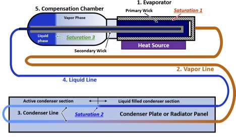
The LHP consists of five major components shown in the figure below:
- Evaporator. The evaporator performs heat acquisition function. The liquid phase in the evaporator absorbs heat while it is converted into vapor. The evaporation process occurs at the outer surface of the primary wick structure shown in figure below. There is a saturation condition in the evaporator.
- Vapor line provides a passage for a vapor flow to the condenser.
- Condenser is where vapor converts back into liquid. The latent heat of the working fluid is released in the active condenser section. So, the active section of the condenser is at saturation temperature. The liquid is subcooled in the remaining part of the condenser. This liquid subcooling compensates parasitic heat leaks into the liquid return line and compensation chamber. The liquid subcooling occurs naturally and adjusts as necessary during the LHP operation. An LHP condenser is attached to a radiator in a typical space application.
- Liquid line is necessary to return liquid back to the evaporator.
- Compensation chamber acts as a reservoir where additional liquid phase is being stored. The liquid in the compensation chamber is supplied to the evaporator via secondary wick structure as needed to accommodate operating condition and transients. The compensation chamber always contains two phases: liquid and vapor. Therefore, working fluid in the compensation chamber is at saturation.
Recent articles on LHPs published by GSFC include:
- Semenov, S., Patel, D., Hoang, T., Stull, C., "Thermal Ground Testing of Loop Heat Pipes for PACE OCI," ICES-2022, 51st International Conference on Environmental Systems, 10-14 July 2022, St. Paul, MN
- Ku, J., "Temperature Oscillations in Loop Heat Pipes - A Revisit." STCW, March 2018, El Segundo, CA
- Ku, J., Garrison, M., Robinson, F., Ottenstein, L., "Loop Heat Pipe Temperature Oscillation Induced by Gravity Assist and Reservoir Heating," ICES—2015, 45th International Conference on Environmental Systems, 12-16 July 2015, Bellevue, WA
GLAS Loop Heat Pipe
The GLAS spacecraft is designed to obtain ice sheet and ocean topography, and global profiles of land and vegetative canopy. GLAS utilizes three lasers, each of which dissipates approximately 100 W when operating, and only one laser is needed at a time. A heat pipe/LHP system was proposed for thermal control. A prototype LHP was manufactured by Dynatherm Corporation, Inc.
The GLAS LHP has a cylindrical evaporator with a diameter of 25.4 mm and a length of 150 mm. The evaporator's envelope is constructed of low carbon steel, and it uses a sintered nickel wick with an effective pore radius of less than 1.2 micron. The compensation chamber has a diameter of 46 mm and a length of 76 mm. Both the liquid and vapor transport lines are approximately 460 mm long each. They are made from smooth wall tubing with a diameter of 5.54 mm and a wall thickness of 0.51 mm. The condenser is a single pass, direct condensation heat exchanger type with a total length of 4.06 m and a condenser tube diameter of 5.54 mm. It is made from an extruded small diameter aluminum tubing with an integral fin. The condenser tubing is bent into serpentine shape, which makes passes across a radiator panel. The heat exchanger is mounted to the radiator panel similar to that proposed for GLAS. A copper saddle is attached to the evaporator's envelope to hold three cartridge heaters.
For more information:
Article published by GSFC
Douglas, D., Ku, J., and Kaya, T., "Testing of the Geoscience Laser Altimeter
System (GLAS) Prototype Loop Heat Pipe," AIAA Paper 99-0473, January 1999.
Contact
Project Manager - JenTung Ku
GSFC Code 545.2
(301)
286-3130
JenTung.Ku-1@nasa.gov
Donya Douglas-Bradshaw
GSFC Code 545.2
(301)
286-6952
Donya.M.Douglas-Bradshaw@nasa.gov
Bio-Capillary Pumped Loop
Introduction and Summary
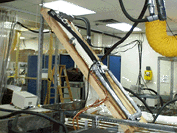
A Bio-Glove Loop Heat Pipe, designed to heat the hands using heat from the body's trunk, was developed, fabricated, and tested. The LHP consists of an evaporator designed to mount under the arm, a condenser which was sewn into a two-layer glove, and flexible liquid and vapor transport lines running along the arm and connecting the evaporator and condenser. The work was performed in several stages under contract to NASA Goddard Space Flight Center.
Contact
Ted Swanson
(301) 286-8168
Theodore.D.Swanson@nasa.gov
NRL Loop Heat Pipe Experiment
The NRL Loop Heat Pipe (LHP) has a cylindrical evaporator of 25.4 mm in diameter and 305 mm in length. The compensation chamber has the same diameter as the evaporator, and is 127 mm long. A sintered nickel wick with an effective pore radius of less than 1.2 micron is used. The liquid and vapor transport lines are made of 4.8 mm outer diameter stainless steel tubing, and has an overall length of about 1524 mm each. The condenser consists of three separate sections linked in series. It is made up of 4.8 mm outer diameter stainless steel tubing with an overall length of 2032 mm. The condenser is a single pass and direct condensation heat exchanger. However, no radiator panel is employed. The condenser line is attached to the coolant loop by small aluminum saddles and epoxy fillings are used between the tubes to minimize the thermal contact resistance. The evaporator is embedded into an aluminum saddle so that heat could spread evenly on the upper side of evaporator.
For more information:
Recent article published by GSFC
Cheung, M. K., Hoang, T. T., Ku, J., and Kaya, T., "Thermal Performance and Operational
Characteristics of Loop Heat Pipe (NRL LHP)," SAE Technical Paper Series, Paper No. 981813,
July 1998.
Contact
Sergey Semenov
GSFC Code 545
(301)
286-3130
Sergey.Y.Semenov@nasa.gov
Cryogenic Capillary Pumped Loops
How the Loop Works
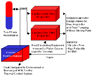
This schematic diagram illustrates the operation of a cryogenic capillary pumped loop. Here is cycle that the working fluid goes through:
- The working fluid is stored in the accumulator, the tank shown by the oval on the left side of the figure.
- Liquid flows from the accumulator (or from the heat exchanger) to evaporators attached to the equipment to be cooled, shown in the figure by red boxes. The liquid absorbs heat as it evaporates.
- The vapor flows to the heat exchanger, shown by the box drawn in red and blue. The "hot" vapor flows into the red section and cools as it flows through the blue section. The heat exchanger dumps heat to a radiator, cryocooler, or other part of the thermal system.
- The recondensed liquid flows from the heat exchanger to start the cycle over.
Advantages of the Capillary Pumped Loop
- Vibration free
- No ElectroMagnetic Interference (EMI)
- Flexibility in positioning of heat generating electronics away from heat exchangers, radiators, cryocoolers, etc.
- As shown in the next figure, one group of cryocoolers can cool several sensors in different parts of the spacecraft.
Contact
Mark Kobel
GSFC Code 545
(301)
286-8832
Mark.C.Kobel@nasa.gov
See also "Flight Testing of a Cryogenic Capillary Pumped Loop", IECED-99-042, 34th Intersociety Engineering Conference on Energy Conversion Vancouver, British Columbia, August 1-5, 1999, by Jentung Ku and Mark Kobel (NASA/GSFC), David Bugby and Edward Kroliczek (Swales Aerospace), and Jane Baumann and Brent Cullimore (C & R Technologies, inc.)
Thermal Energy Management Processes (TEMP 2A-3)
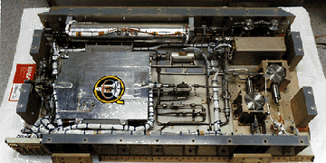
The Thermal Energy Management Processes (TEMP) 2A-3 experiment was a mechanically pumped two-phase ammonia thermal control system. The experiment flew on the STS-46 shuttle flight in August 1992. It flew along with the JSC EOIM-III materials experiment, mounted on a shuttle bridge structure (shown in photo below). The TEMP experiment performed well and all mission objectives were met. Valuable data has been obtained on the micro-gravity effects on two-phase pressure losses, heat transfer coefficients, and fluid management techniques. This data will be used for the design of thermal control systems on Space Station and EOS.
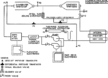
The TEMP 2A-3 experiment consists of several components shown in the schematic above. Two cold plates are used to transfer heat to the ammonia fluid in the evaporator mode and remove heat from it in the condenser mode. A two-phase reservoir based on propulsion tank design controls system temperature level and maintains the proper fluid inventory in the loop. Two mechanical pumps circulate the liquid ammonia with flow meters measuring the flow rate. The boiling experiment measures heat transfer coefficients in two-phase regimes while the pressure-loss experiment examines two-phase pressure drop in a 3/16 inch O.D. line. The radiator provides heat rejection for vapor condensation and also serves as the experiment component mounting surface. A valve is used to change from the evaporator mode to the condenser mode by diverting the flow to the condenser plate. This tests the heat removal capability of the system. Heaters were used on the evaporator cold plate to simulate heat loads from an electronics box or instrument. Thermistors and pressure transducers were used to obtain temperature and pressure data.
The TEMP experiment was controlled and monitored in real time from a Payload Operations and Control Center located at JSC. Experiment tests included: power levels ranging from 45 watts to 900 watts, operating temperature ranges from 21 C to 35 C, and flow rates ranging from 1 Kg/hr to 8 Kg/hr. Real time replanning allowed us to obtain additional important data as well. This included operation during four OMS thruster firings that are used to change the altitude of the shuttle. The TEMP experiment functioned nominally during these events, thus demonstrating proper operation while the spacecraft is being maneuvered. Also, a long duration (15 hour) low power test was conducted to show system reliability for long term operations. Comparison of the flight data to ground test data is favorable, with no major anomalies noted.
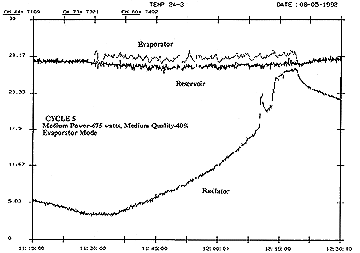
A sample of the flight data is shown in the figure above. The reservoir temperature is set at 28 C and 675 watts of power is applied to the evaporator at hour 11:30. The evaporator temperature increases to 30 C, when ammonia vaporization occurs, thus maintaining the temperature at 30 C. There is a slight elevation of the evaporator temperature above the reservoir due to the temperature gradients within the evaporator plate structure. The radiator temperature gradually increases as it absorbs the heat load from the evaporator. Eventually the heat was shut off at hour 12:20 when the radiator could no longer accept the heat load. Future larger flight systems will employ radiators that are capable of handling these heat loads on a continuous basis.
One noticeable effect of micro-gravity on the TEMP experiment was an increased level of flow oscillations while it was running. This led to additional cold fluid movement into the reservoir, and thus the reservoir controlled the system temperatures 1/2 to 1 degree C cooler than on the ground in some cases. The TEMP functioned nominally, and this is not considered a severe adverse effect since the reservoir temperature set point can be increased by ground command to compensate for this effect. Another micro-g effect was a reservoir dry-out at low power conditions, which had not been observed on the ground. Future reservoir designs will use wicking devices and additional ammonia inventory to alleviate this effect.
Examination of the pressure loss data showed no dramatic increases in pressure drops in micro-gravity for two-phase systems (although there was a substantial increase in flow oscillations). However, the TEMP 2A-3 used relatively small diameter 3/16 and 1/4 inch O.D. tubing, so the results are limited to this case (annular flow). Results for larger diameter tubing may show a stronger gravitational effect, depending on flow quality, flow rates, and the resulting flow regimes. The data from the boiling experiment showed temperatures slightly higher than that observed on the ground, thus yielding marginally lower evaporative heat transfer coefficients in microgravity.
References:
- Butler, D., Kedzierski, R., and Grote, M., 1993, "Thermal Energy Management Processes (TEMP 2A-3) Flight Experiment," SAE Paper No. 932300.
- Reinarts, T., Ungar, E., and Butler, D., 1995, "Adiabatic Two-Phase Pressure Drop in Microgravity: Temp 2A-3 Flight Experiment Measurements and Comparison with Predictions," AIAA Paper No. 95-0635.
- Didion, J., and Butler, D., 1993, "Comparison and Analysis of Ground and Flight Data for the TEMP 2A-3 Boiler Experiment," National Heat Transfer Conference, ASME 93-HT-28.
- Grote, M., Stark, J. A., Butler, D., and R. McIntosh, 1987, "Design and Test of a Mechanically Pumped Two-Phase Thermal Control Flight Experiment," AIAA Paper No. 87-1629.
Item 2 is available from the AIAA (a non-government site).

NASA Goddard Thermal Engineering Branch
Updated: August 2024
NASA Official: Veronica Otero
Website Manager: Elliot Schwartz
